

Skip to content
CallGet a site assessment
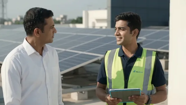
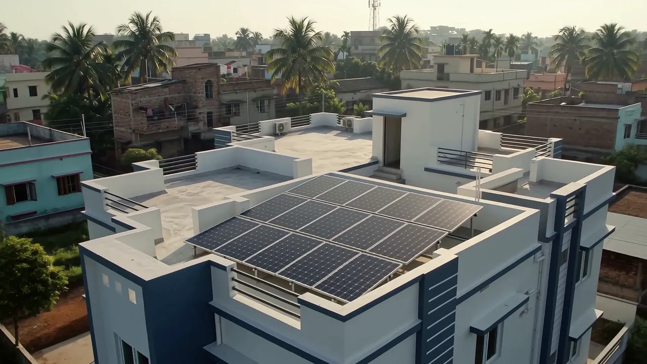
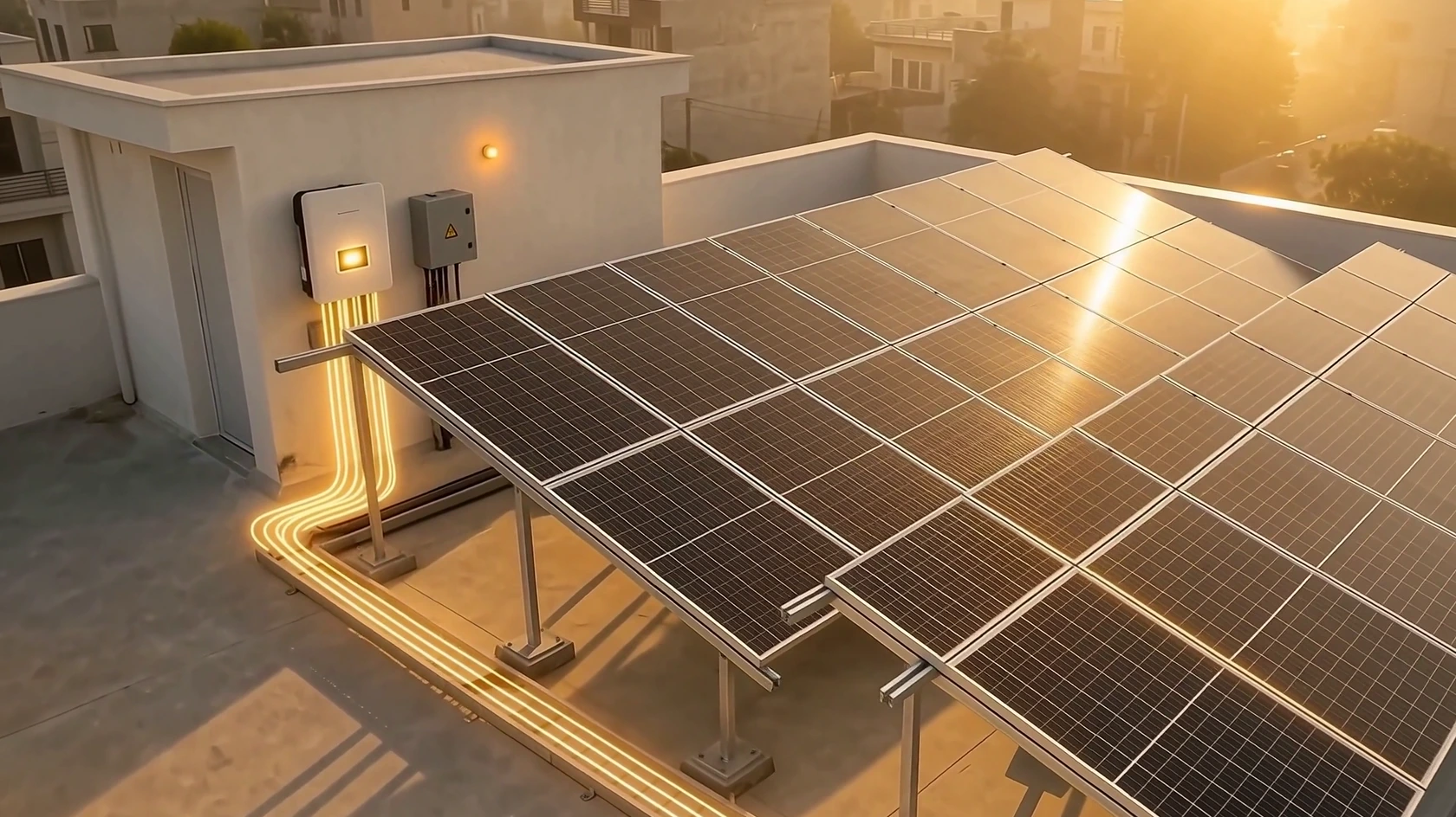
Concept visualisation of a finished rooftop solar array in morning sun, with an inverter on the wall of the stair room.

Solar engineering · installation · maintenance

Power from your own roof.

End-to-end solar for homes and businesses — on-grid, off-grid and hybrid systems, engineered, installed and maintained by AKE Power.

  1. 01Consult
  2. 02Engineer
  3. 03Install
  4. 04Maintain
Concept visualisation

What AKE Power does

  • End-to-endSolar
  • On-gridSystems
  • Off-gridSystems
  • HybridSystems
  • Long-termCare
  1. Sunlight, the original power source

    Every leaf is a solar panel.

    A tree spends its whole life catching sunlight and turning it into energy. Solar panels do the same job on your roof, and turn that light into electricity.

  2. From canopy to array

    Your roof can work the same way.

    On-grid, off-grid or hybrid: AKE Power engineers the system for your site, installs it and keeps it maintained.

  3. Start with your site

    Plant yours with a site assessment.

    Tell us about your roof and your electricity use, and we will look at what your site can support.

    Request a site assessment

About AKE Power

One team from first visit to long-term care.

AKE Power is a full-service solar solutions provider for engineering, installation and maintenance, and a unit of Kalpana Power Tech Private Limited.

We design and build on-grid, off-grid and hybrid systems for residential, commercial and industrial sites, and stay involved after the system is switched on.

  1. A technician and a homeowner smiling over a tablet at a wooden table on a verandah.Illustrative visual

    Listen

    Consultation

    We start with your electricity use, your site and what you want the system to do — lower grid consumption, backup, or running without a grid connection.
  2. An engineer and a site technician talking as they walk beside a large rooftop array on a commercial building.Illustrative visual

    Design

    Engineering

    System type, layout, structure and electrical design are worked out for the specific roof or site, not taken from a template.
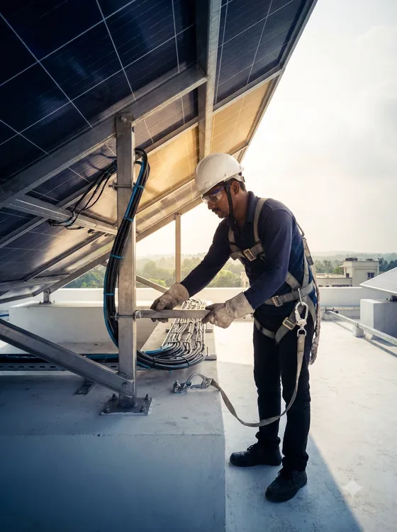
  3. A technician in a hard hat, safety glasses and fall-arrest harness securing cabling beneath a raised array.Illustrative visual

    Build

    Installation

    Mounting, modules, cabling, protection and inverter work carried out on site, then inspected before the system is commissioned.
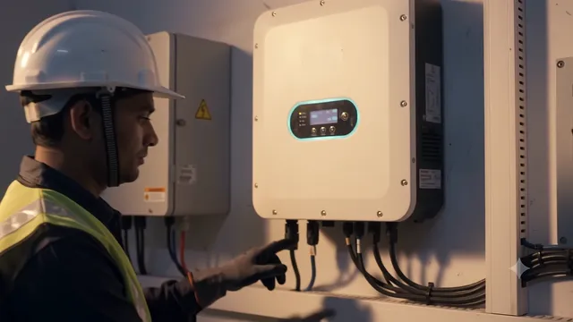
  4. A technician in a hard hat inspecting a wall-mounted inverter and checking its cable connections.Illustrative visual

    Care

    Maintenance

    Inspection and upkeep after handover, so the system stays safe and keeps generating the way it was designed to.

Our network

Brands we work with

Trademarks belong to their respective owners and are shown for identification only.

  • Rudra Group

Roof to power

How a rooftop system comes together

  1. Survey the roof

    We assess the usable roof area, its orientation and how shade falls across it through the day, along with the structure and the existing electrical setup.

  2. Install the mounting structure

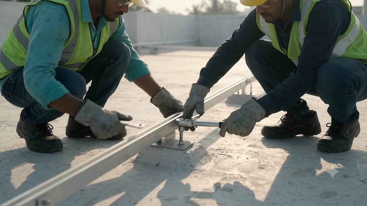
    The structure is set out to the design and fixed to suit the roof type, so the array sits at the planned tilt and is held securely.

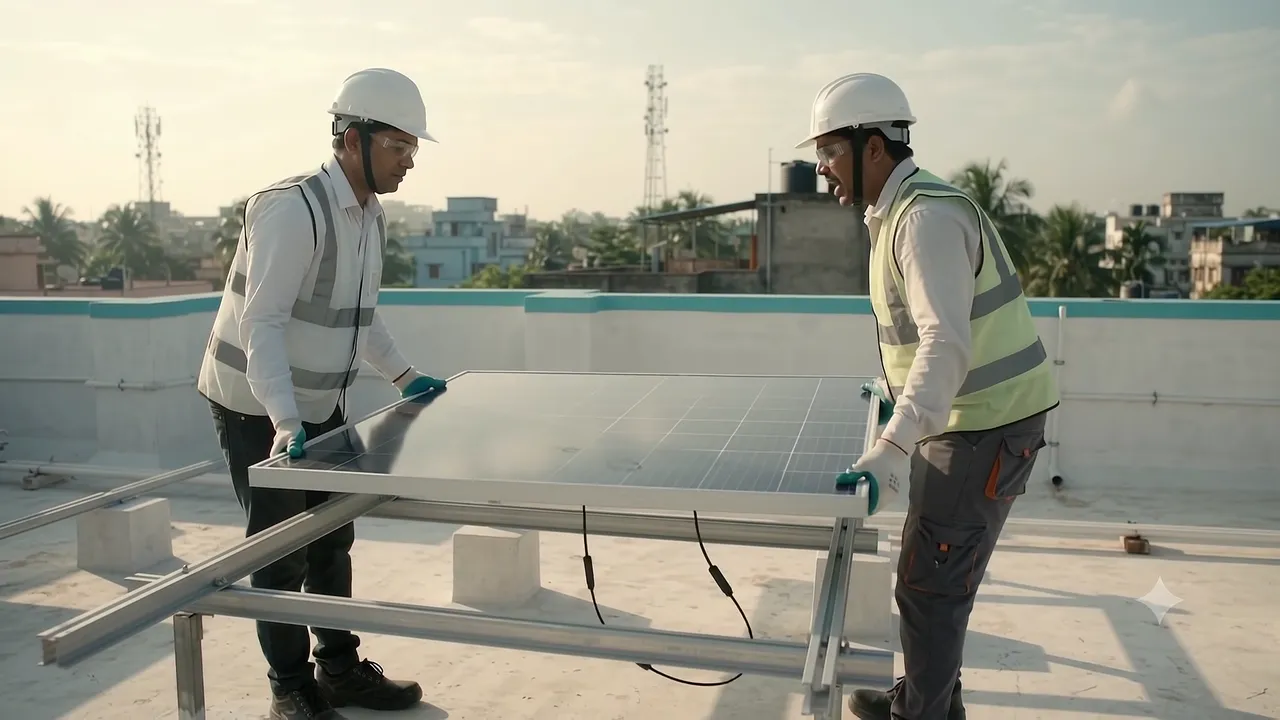
  3. Place and secure the panels

    Modules are lifted onto the structure, aligned row by row and clamped in place.

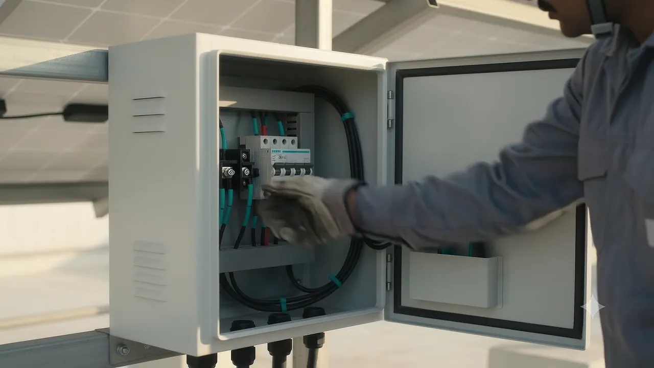
  4. Connect and inspect

    Cables are routed and protected along the structure, terminated through combiner and protection equipment to the inverter, then checked before switch-on.

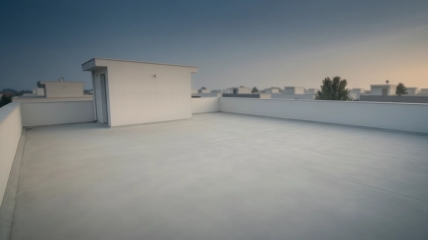
  5. The finished rooftop

    The system is commissioned and handed over, with maintenance visits to keep it safe and working as designed.

Roof to power

How a rooftop system comes together

  1. Illustrative visual

    Step 01

    Survey the roof

    We assess the usable roof area, its orientation and how shade falls across it through the day, along with the structure and the existing electrical setup.

  2. Illustrative visual

    Step 02

    Install the mounting structure

    The structure is set out to the design and fixed to suit the roof type, so the array sits at the planned tilt and is held securely.

  3. Illustrative visual

    Step 03

    Place and secure the panels

    Modules are lifted onto the structure, aligned row by row and clamped in place.

  4. Illustrative visual

    Step 04

    Connect and inspect

    Cables are routed and protected along the structure, terminated through combiner and protection equipment to the inverter, then checked before switch-on.

  5. Illustrative visual

    Step 05

    The finished rooftop

    The system is commissioned and handed over, with maintenance visits to keep it safe and working as designed.

From our sites

On site with AKE Power

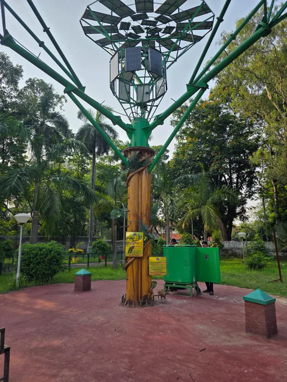
Photos and clips from AKE Power installations: rooftop and shed arrays, raised structures, a solar tree, ground-mounted frames, and the inverter and battery rooms behind them.

See every photo and clip
  • AKE Power project

    Raised array walk-through

  • A green steel solar tree in a park, a canopy of modules raised on a sculpted trunk, with an equipment cabinet beside it.AKE Power project

    Solar tree

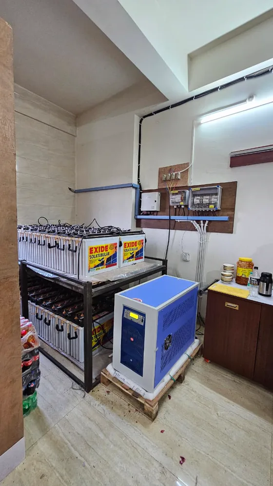
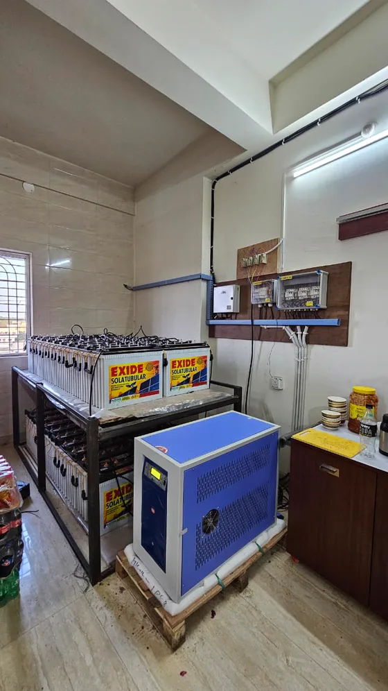
  • Two tiers of tubular batteries on a steel rack beside a blue inverter cabinet, with wall-mounted protection boxes and cable trunking.AKE Power project

    Battery bank and inverter

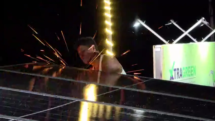
  • AKE Power project

    Night work on an array

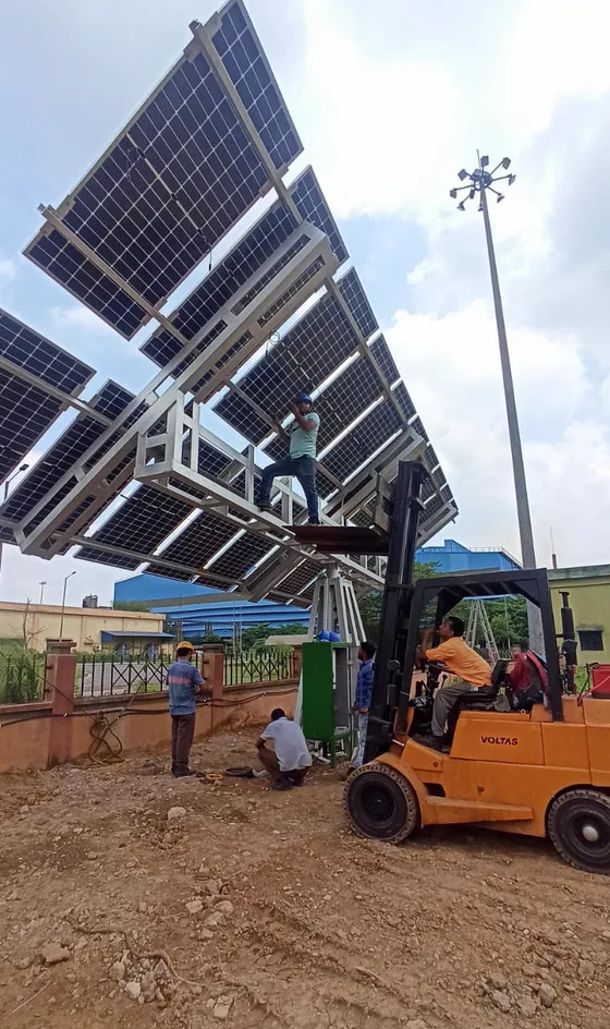
  • Technicians fitting modules to a large elevated ground-mounted frame, one working from a forklift platform.AKE Power project

    Fitting a ground-mounted frame
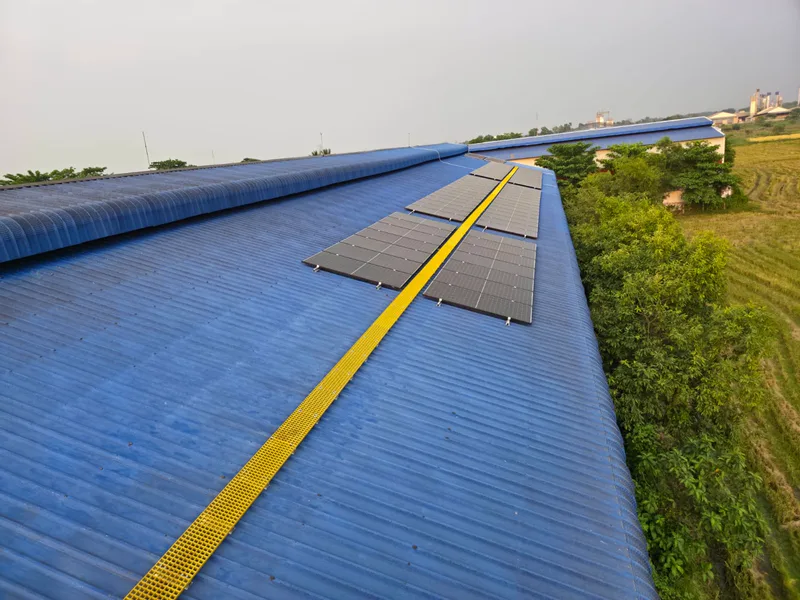
  • Two blocks of solar modules on a long blue metal shed roof, a yellow walkway running between them, with trees and fields alongside.Array on an industrial shed roof
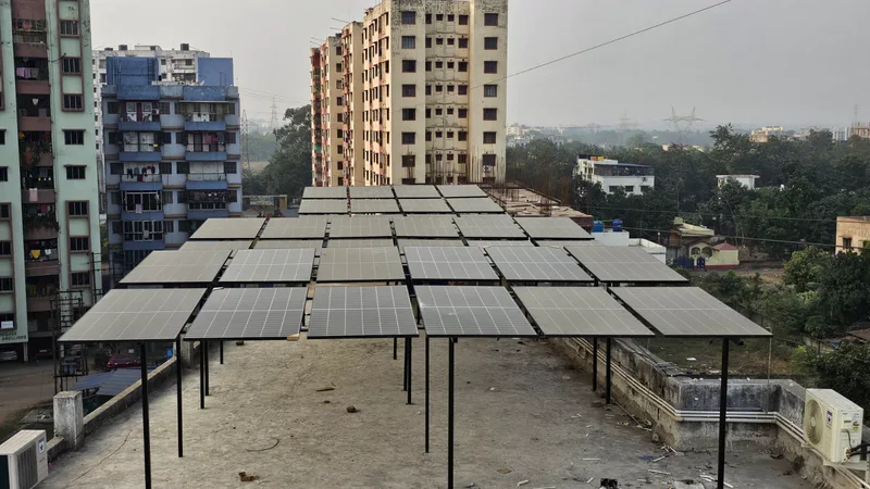
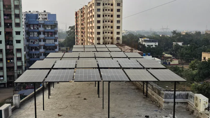
  • Rows of solar modules on a raised steel structure above a flat rooftop, apartment blocks behind.Raised rooftop structure
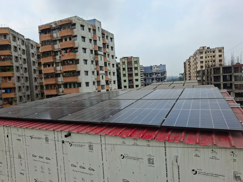
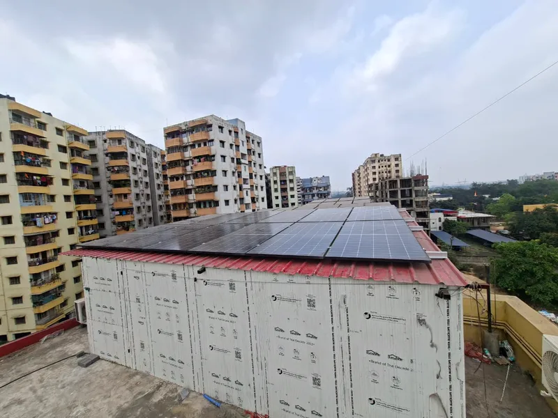
  • Solar modules covering the red sheet roof of a rooftop shed, apartment blocks around it.Array on a rooftop shed
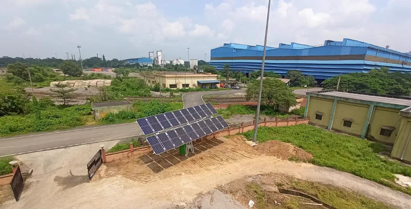
  • A ground-mounted array on a raised frame inside a fenced plot beside a road, large industrial buildings behind.Ground-mounted array
  • The battery rack and inverter cabinet seen from the window side, protection boxes on the wall above.Battery room, second view
  • Front view of solar modules on tall steel legs across a flat rooftop, apartment blocks and trees behind.Raised rooftop structure, front view
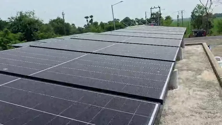
  • Wide view of a rooftop shed with its roof covered in solar modules, under a cloudy sky.Rooftop shed, wide view

AKE Power projectSupplied by AKE Power from their own sites

How solar works

On-grid, off-grid or hybrid?

Every system turns sunlight into electricity with panels and an inverter. What changes is whether it connects to the utility grid and whether it stores energy. Choose a type to compare.

On-grid system

Panels feed an inverter connected to your building's supply and the utility grid. Solar electricity is used on site first; the grid supplies the rest.

Utility grid
Connected
Battery storage
Not included
During a grid outage
A standard grid-connected inverter switches off for safety, so an on-grid system does not provide backup on its own.
Often suits
Sites with a dependable grid supply that want to offset part of their grid consumption.
Ask which type suits your site
Illustrative system diagramSolar panels on the roof connect to an inverter, which supplies the home and connects to the utility grid through a meter.Solar arrayInverterHome loadsBatteryMeterGridIllustrative diagram
Illustrative only — not an engineering drawing. Actual equipment, wiring and protection are designed for each site.

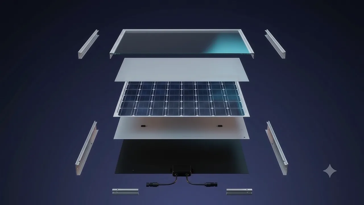
Inside a solar module

What a panel is made of

  1. 1Front glassProtects the cells while letting light through.
  2. 2EncapsulantSheets either side of the cells that bond the layers together and cushion the cells.
  3. 3Solar cellsConvert sunlight into direct-current (DC) electricity.
  4. 4BacksheetSeals and insulates the rear of the module.
  5. 5Aluminium frameGives the module rigidity and the edge that mounting clamps hold.
  6. 6Junction box & leadsWhere the module's cables leave to connect with the rest of the array.
Concept visualisation
Concept visualisation of a typical crystalline module. Layer names are shown as text so they stay readable without the video.

The rest of the system.

Which parts appear depends on the system type and the site.
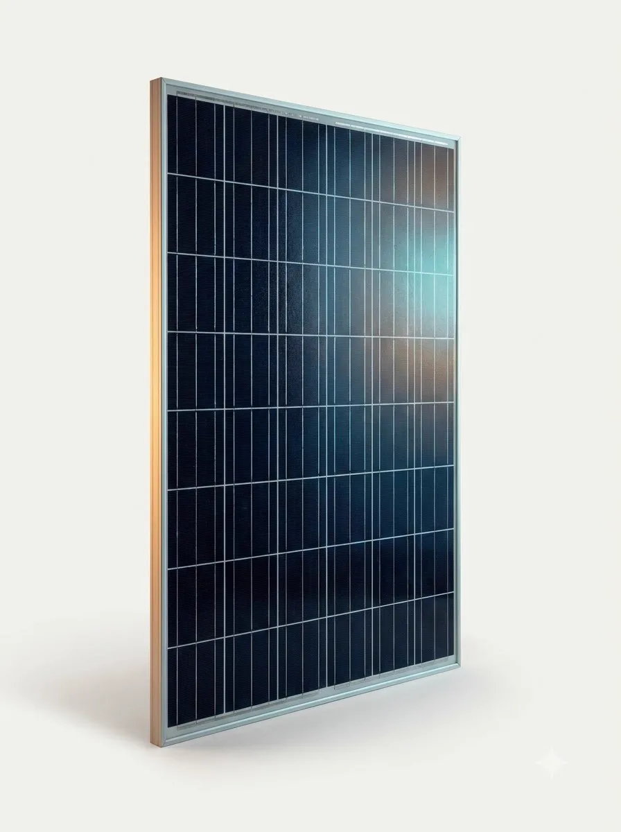
  • A single solar module standing on a plain studio background, light catching its cells.Illustrative visual

    Generates

    Panel / module

    Generates DC electricity from sunlight. Several modules wired together form the array.
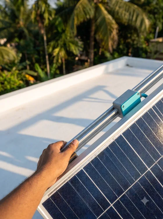
  • Close-up of a hand on the aluminium rail of a solar module, with a teal mounting clamp.Illustrative visual

    Holds

    Mounting structure

    Rails, clamps and supports that hold the array at the designed tilt and keep it secured to the roof.
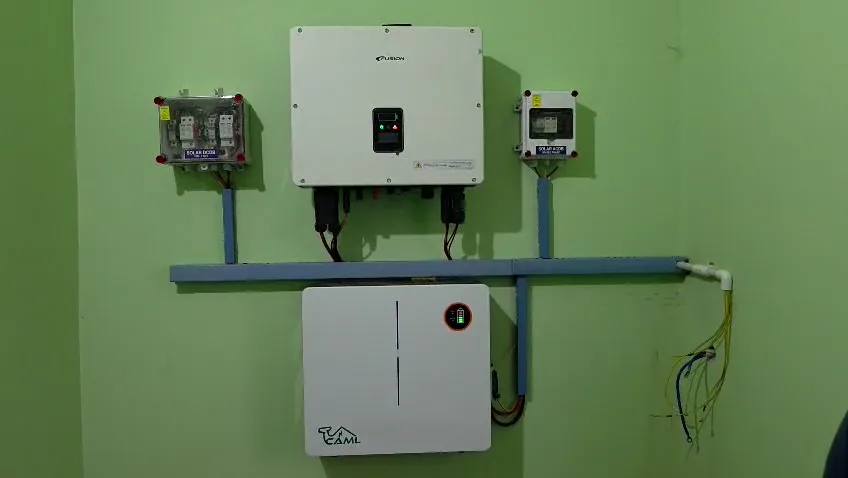
  • A wall-mounted inverter above a battery unit, with protection boxes on either side and cabling run through blue trunking on a green wall.AKE Power project

    Converts

    Inverter

    Converts the array's DC output into AC electricity that the building can use, and manages the system.

  • Two tiers of tubular batteries on a steel rack beside a blue inverter cabinet, with wall-mounted protection boxes and cable trunking.AKE Power project

    Stores

    Battery storage

    Where the design includes it, stores energy for later or for backup. Used in off-grid and hybrid systems.
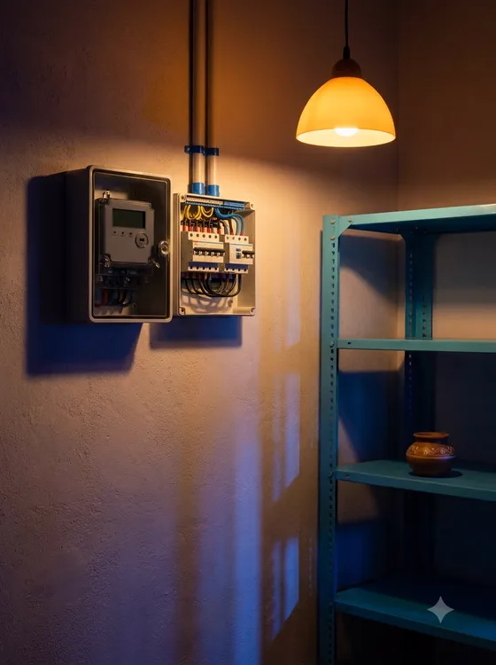
  • An electricity meter and a distribution board with breakers mounted on a wall under a pendant lamp.Illustrative visual

    Measures

    Meter

    Records the electricity exchanged with the utility grid in grid-connected systems.
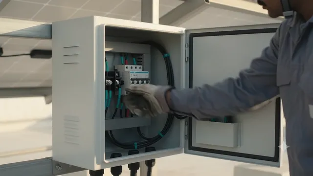
  • A gloved technician routing DC cables along the rails beneath the panels, then working inside an open combiner box.Illustrative visual

    Connects

    Electrical connections

    Cabling, combiner and protection equipment that link every part of the system safely.

Who we build for

Residential, commercial and industrial

Each kind of site asks different questions of a solar system — about space, load, structure and access.
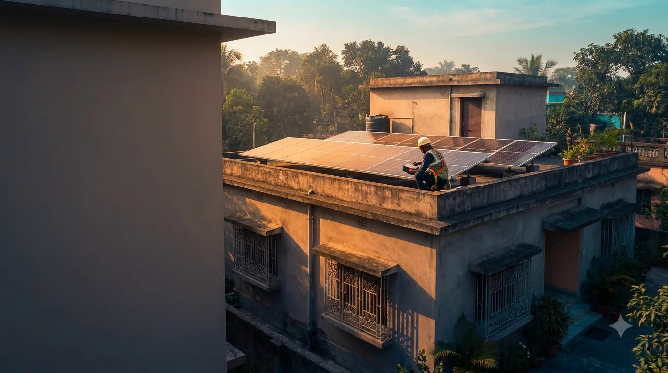
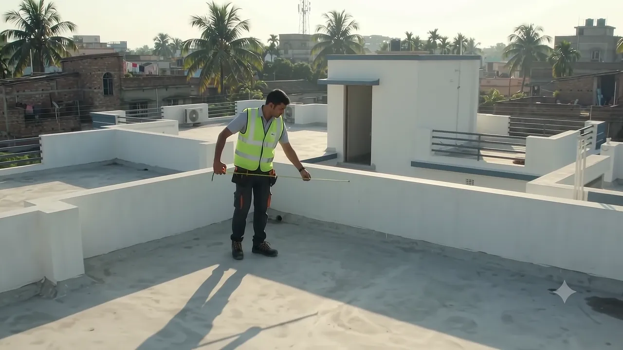
A technician kneeling on the parapet of a residential rooftop array, warm early light across the neighbourhood.Illustrative visual

01 / 03

Residential

Flat terraces, sloped roofs and independent houses.

Systems sized around a household's daytime and evening use, laid out to keep usable terrace space, with storage where backup matters.
  • Terrace and sloped-roof layouts
  • On-grid, off-grid or hybrid
  • Battery storage where designed for backup
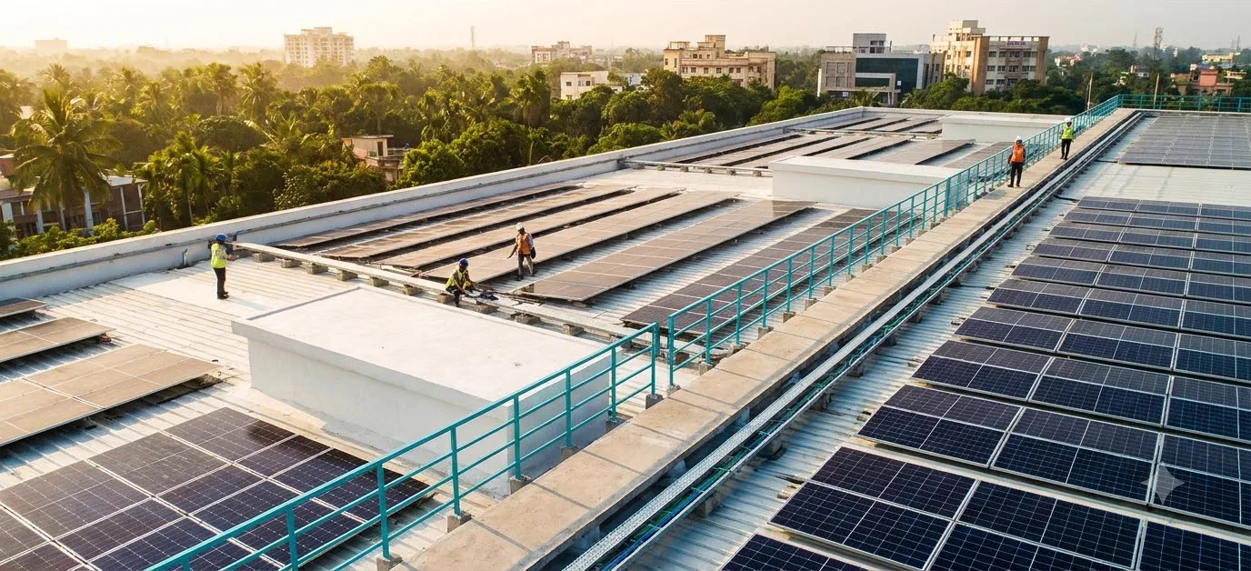
Technicians working across a large commercial metal roof covered in panel rows, with a teal safety railing.Illustrative visual

02 / 03

Commercial

Shops, offices, schools and institutions.

Rooftop arrays planned around business hours, roof access and safety, so generation lines up with when the building uses most power.
  • Metal-sheet and concrete roofs
  • Safe access and walkways
  • Layouts that work around rooftop plant
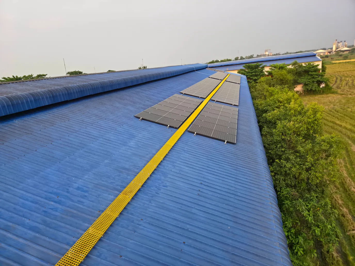
Two blocks of solar modules on a long blue metal shed roof, a yellow walkway running between them, with trees and fields alongside.AKE Power project

03 / 03

Industrial

Factories, warehouses and large sheds.

Larger arrays across industrial roofs, with structural checks, cable routing over long runs and maintenance access built into the layout.

  • Large roof areas
  • Long cable runs and inverter rooms
  • Planned inspection and upkeep

Why solar

Practical reasons, plainly put

  1. 01

    Electricity generated on your own site

    Panels on your roof produce electricity where it is used. How much depends on the roof, its orientation, shade, the season and the system size.

  2. 02

    Less electricity drawn from the grid

    Solar used on site can offset part of your grid consumption. The effect on your bill depends on your tariff, your usage pattern and the utility's rules.

  3. 03

    Stored energy, where the design includes it

    Off-grid and hybrid systems can include batteries, so stored energy is available later in the day or, where designed for it, during a power cut.
Illustrative visual
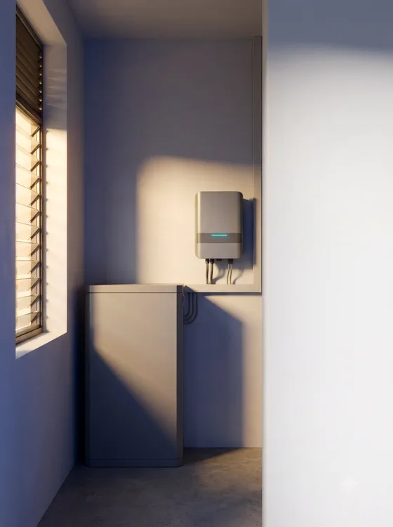
A compact battery unit and a wall-mounted inverter in a daylit alcove beside louvred windows.Illustrative visual
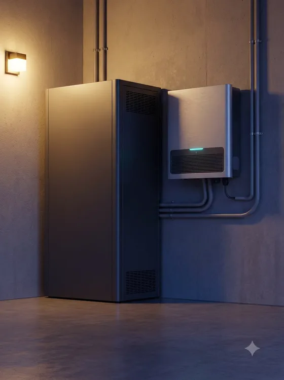
A tall battery cabinet beside a brushed-steel inverter with a teal status light, mounted on a concrete wall at dusk.Illustrative visual

Indicative estimate

Get a rough idea of size and savings.

A starting point for a conversation, not a quote. Drag the sliders or type exact figures; every assumption is shown and you can change it.
How would you like to start?

Use a typical month from your recent bills.

An assumption — replace it with the energy charge on your bill.

How much shade does the roof get?

Shade lowers output. "Some shade" reduces the estimate by 15%; "Not sure" widens the range to allow for up to 25% less.

If given, the size is capped to what this area can hold.

Interested in battery backup?

Doesn't change the generation estimate — storage is sized separately at the site assessment.

Assumptions used (editable)

Daily generation per kW varies with location, season, tilt, orientation and equipment. The range here is a broad planning figure, not a measurement for your site.

Your indicative estimate

System size

—

Share of current use

—

Estimated monthly use

—

Generation, per month

—

Value at your unit cost

—

Indicative only — not a quote, offer or guarantee. Actual generation and savings depend on location, shading, roof orientation and tilt, system design, equipment, tariffs, fixed charges, utility and net-metering rules, and how you use electricity. No subsidy, equipment cost or payback is included.

Send this estimate on WhatsApp

WhatsApp or your email app opens with these figures filled in for you to send. Nothing is sent from this page.